

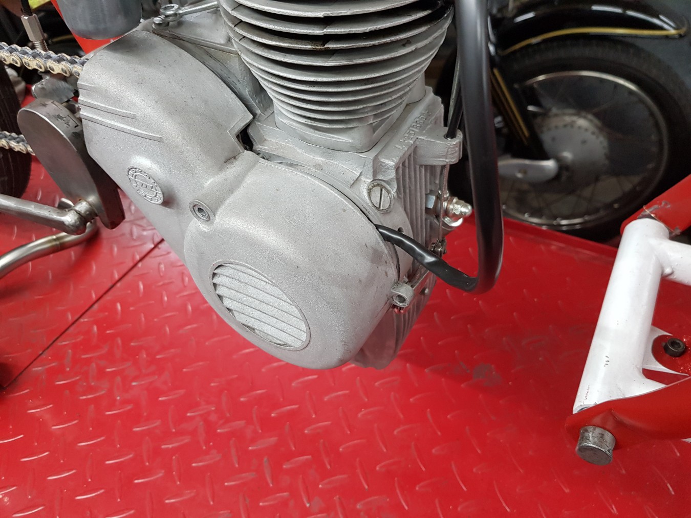
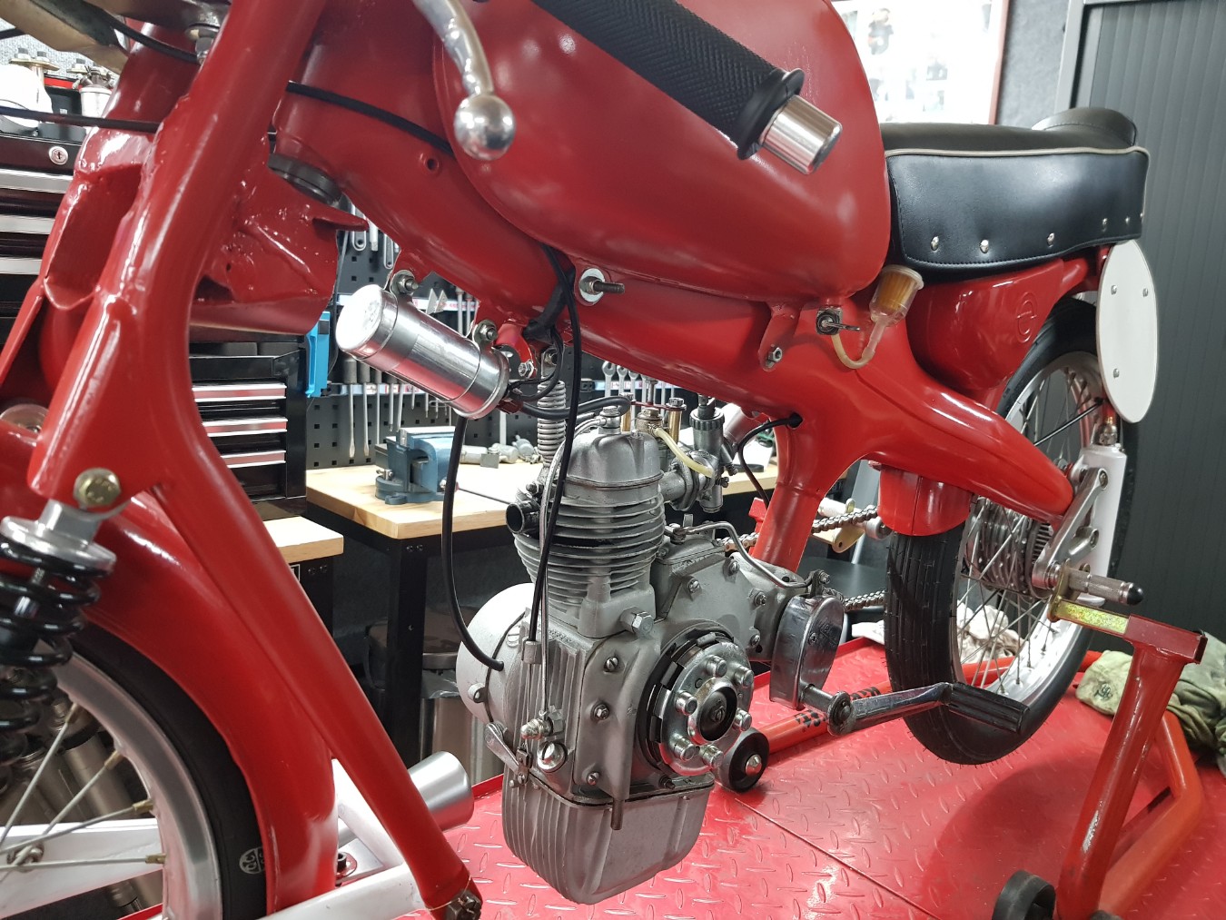
Starting to work out why the ignition is working that bad.
The first step is collecting information, also investigating if its possible for a modern ignition system.
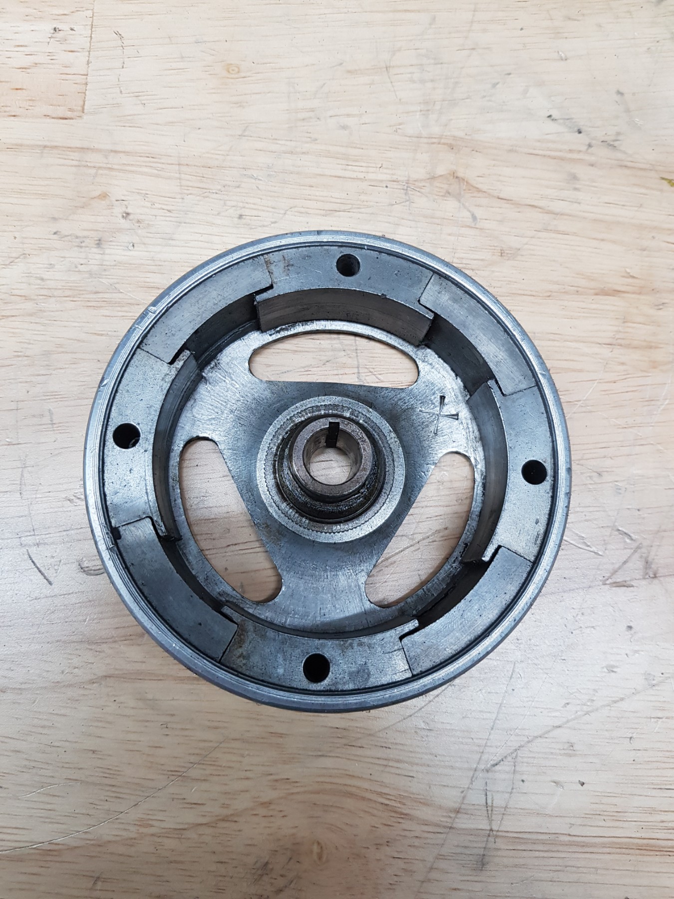
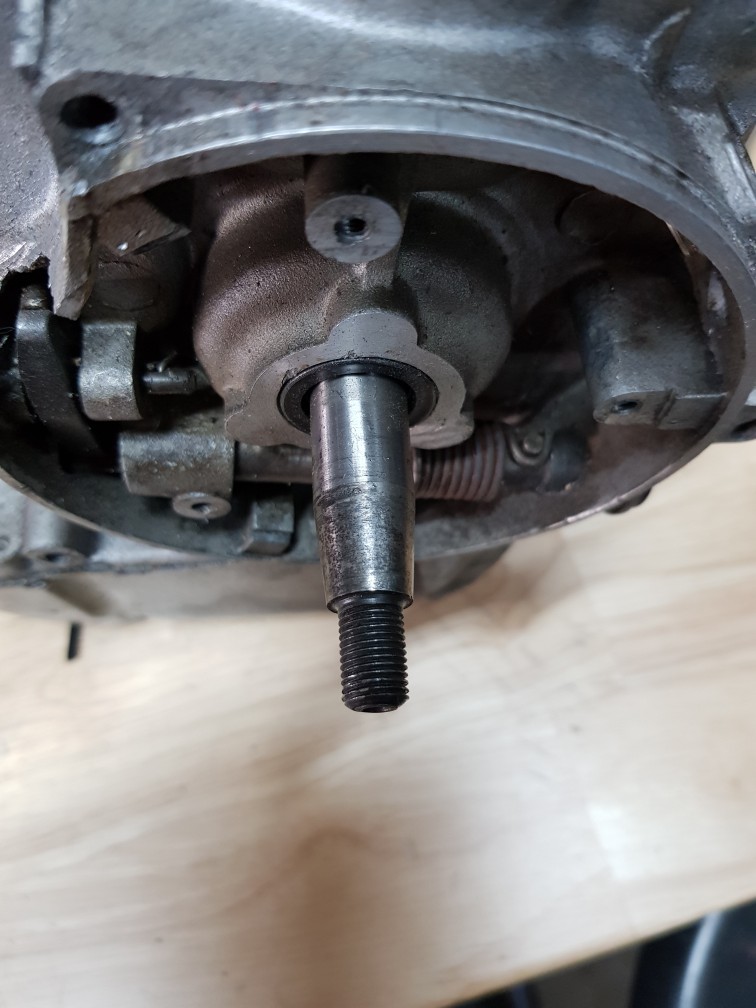
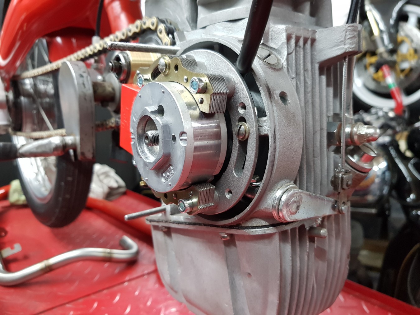
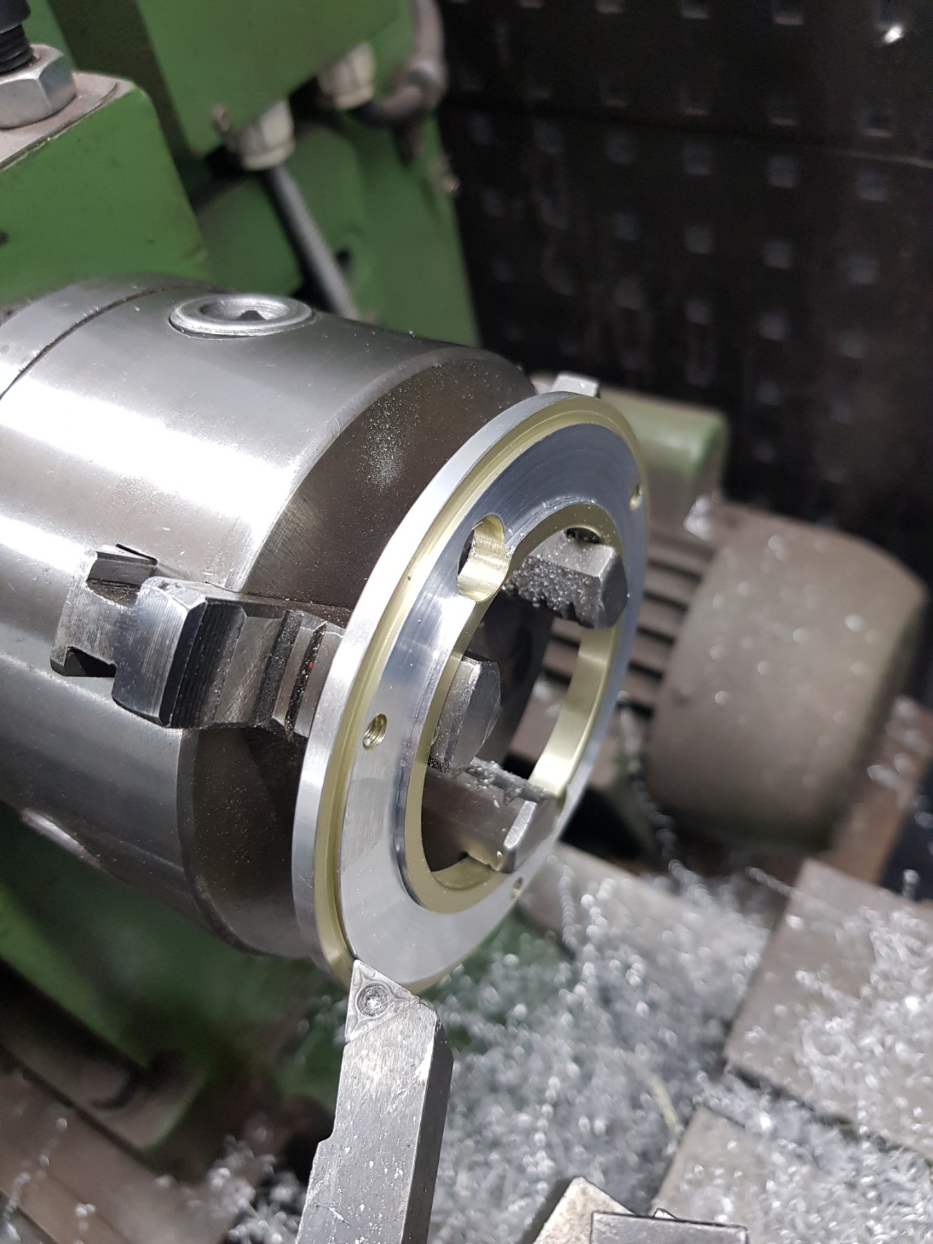
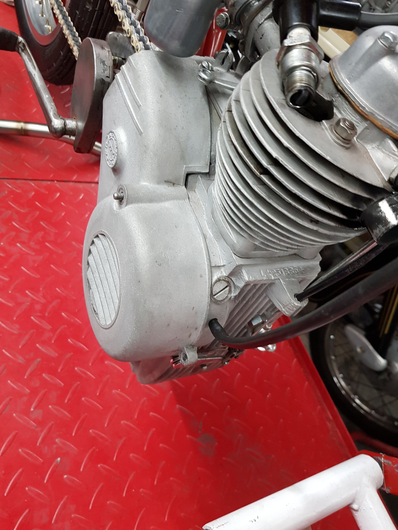
Need to open her up.
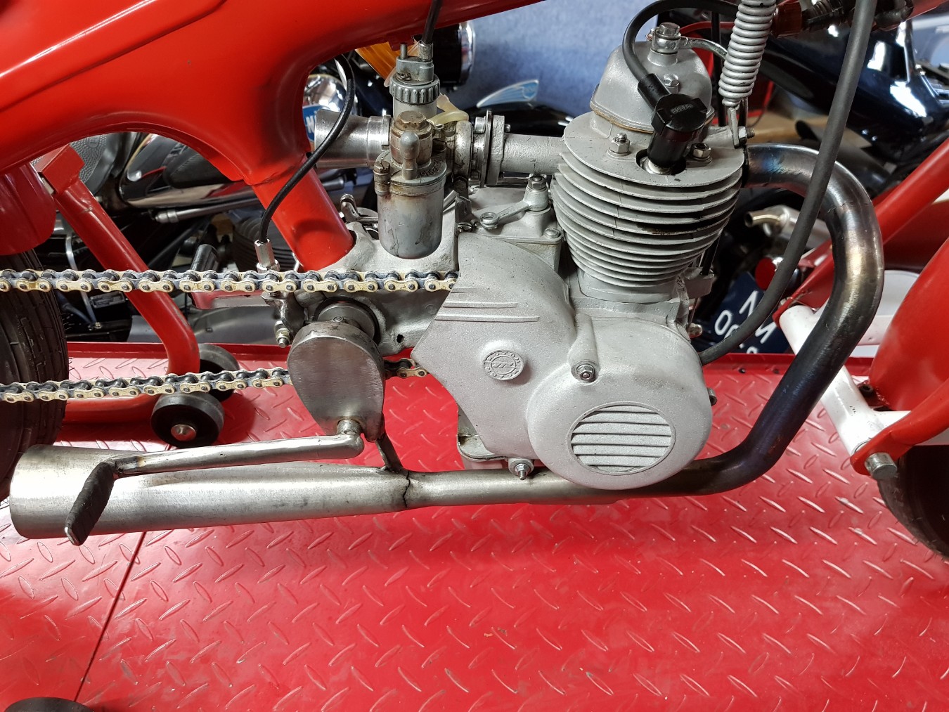
Air gun.
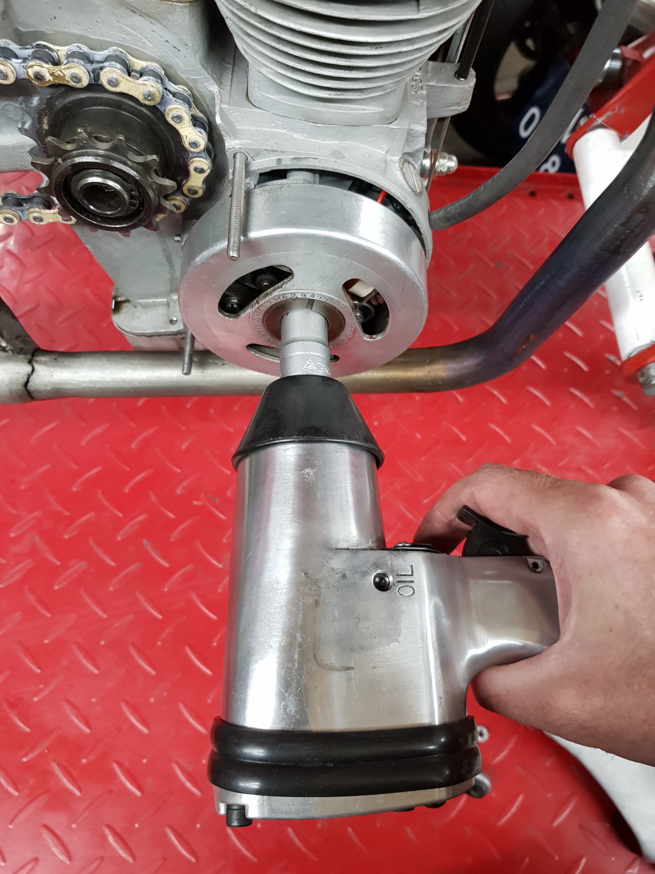
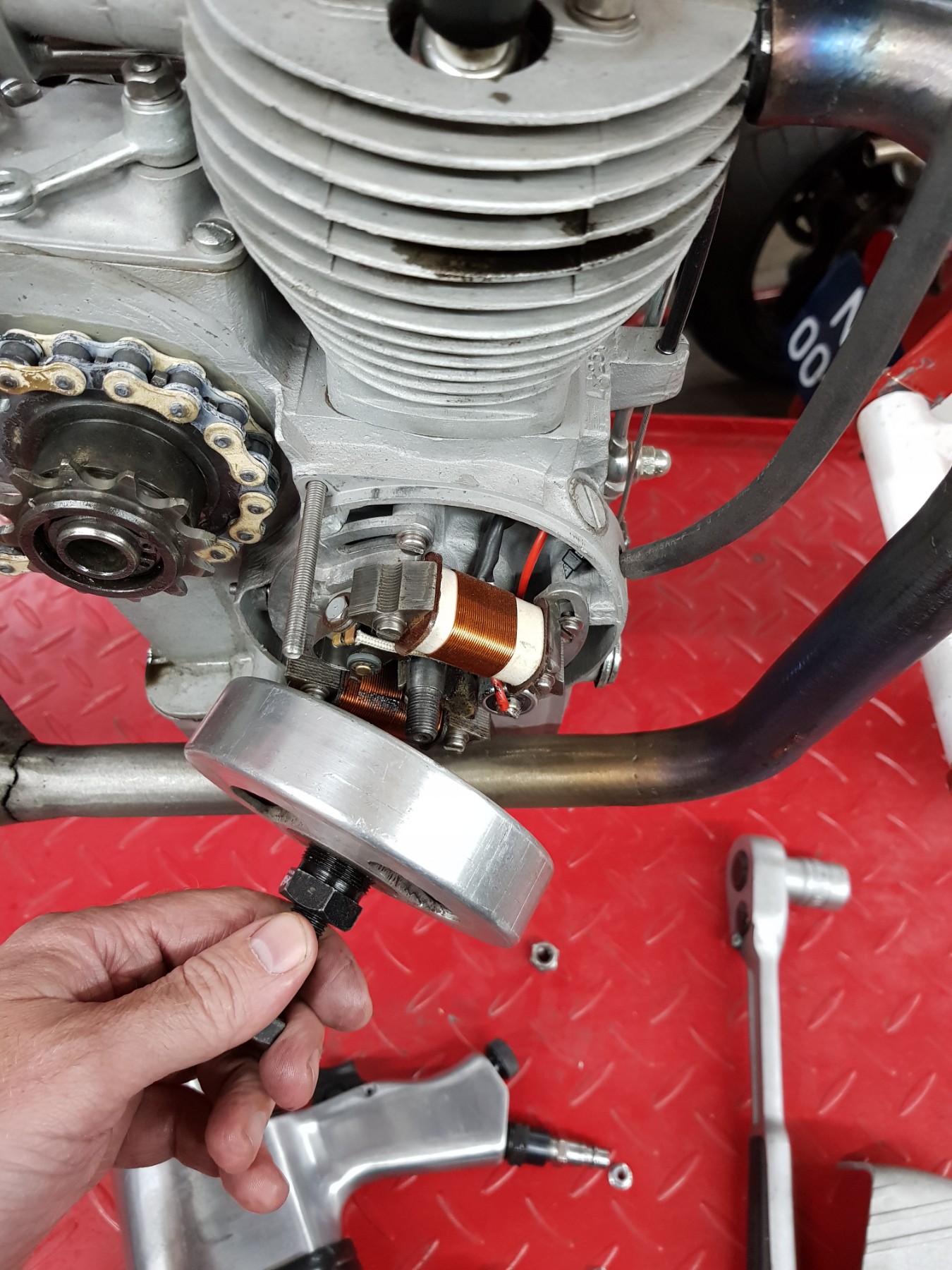
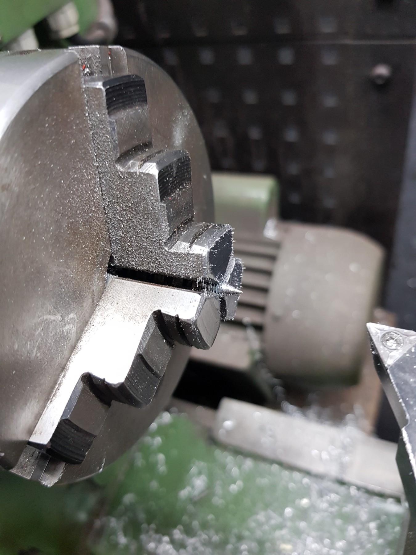
Flywheel extractor.
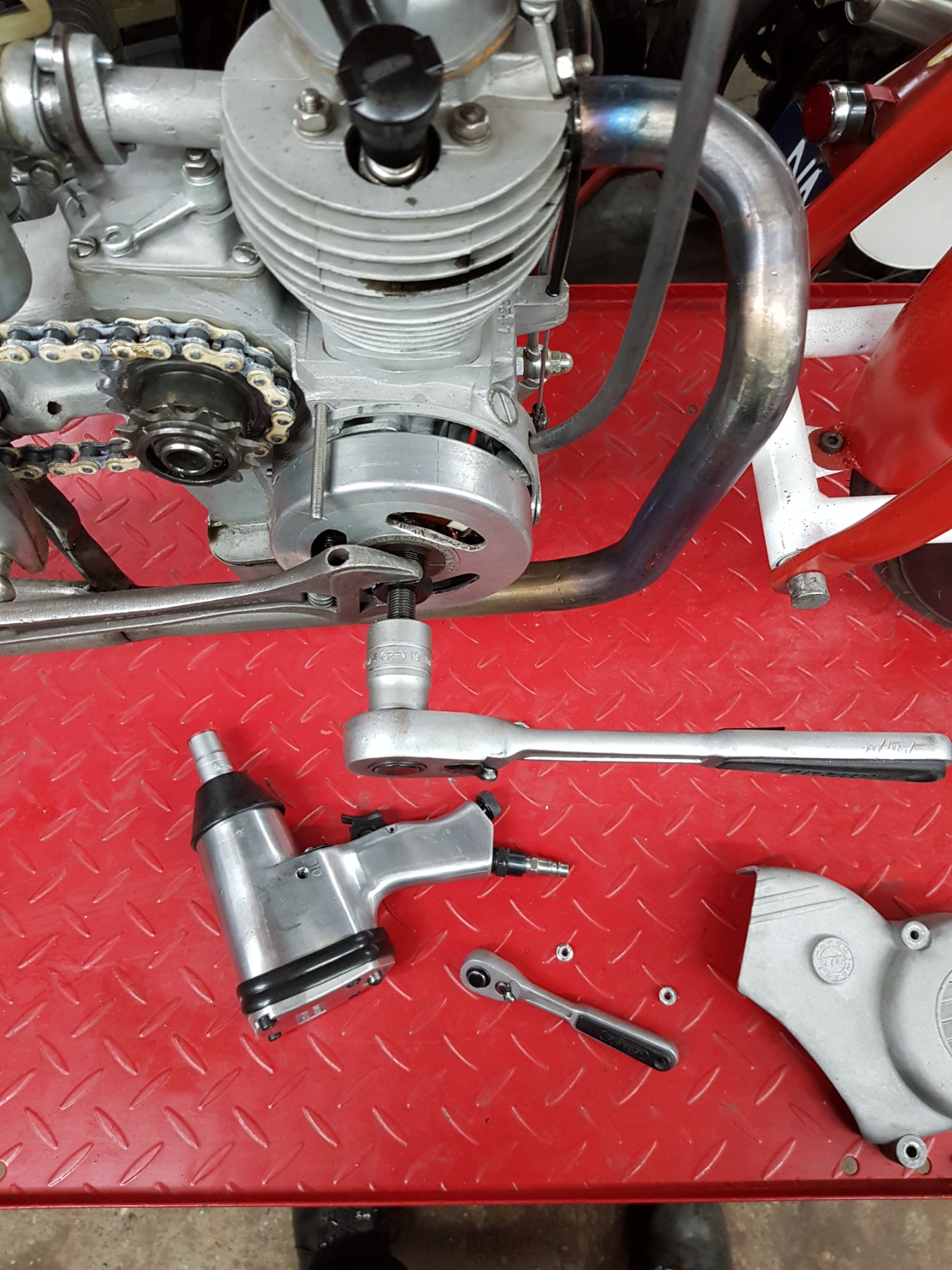
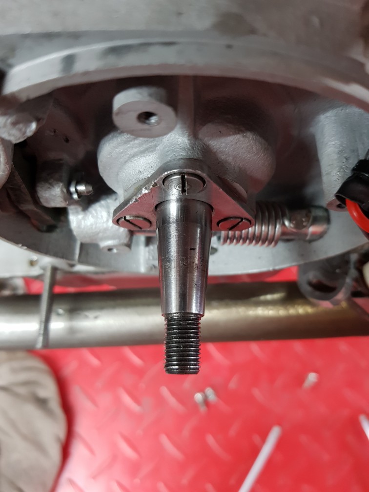
Coming off.
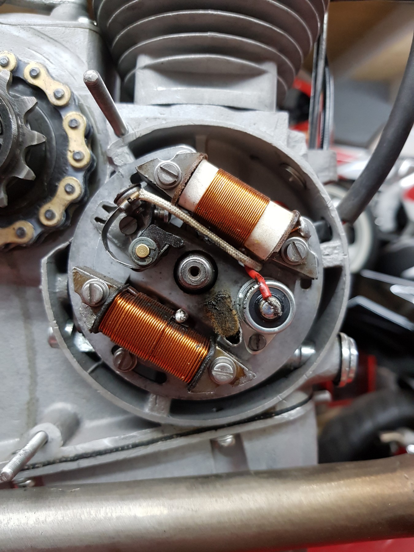
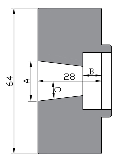
Stator base plate is 94mm
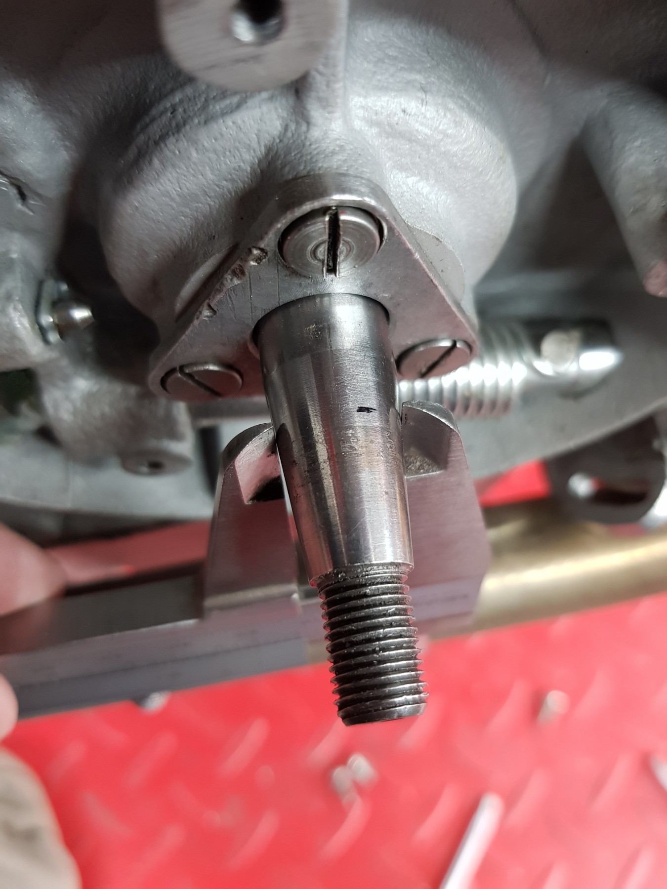
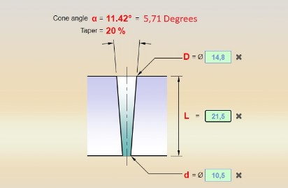
Flywheel end cone is 10,5mm
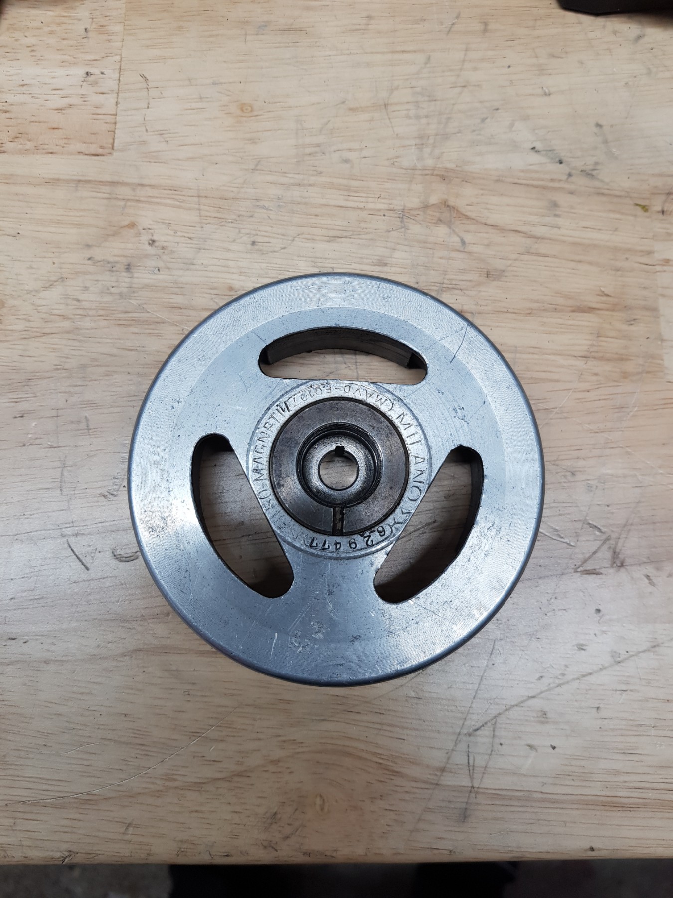
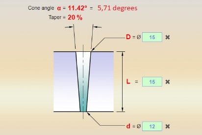
Flywheel end cone 13,1mm
13,65mm marked on tapper.
37,75 - 18,45 = 19,3mm
Here shown 19,3mm on tapper
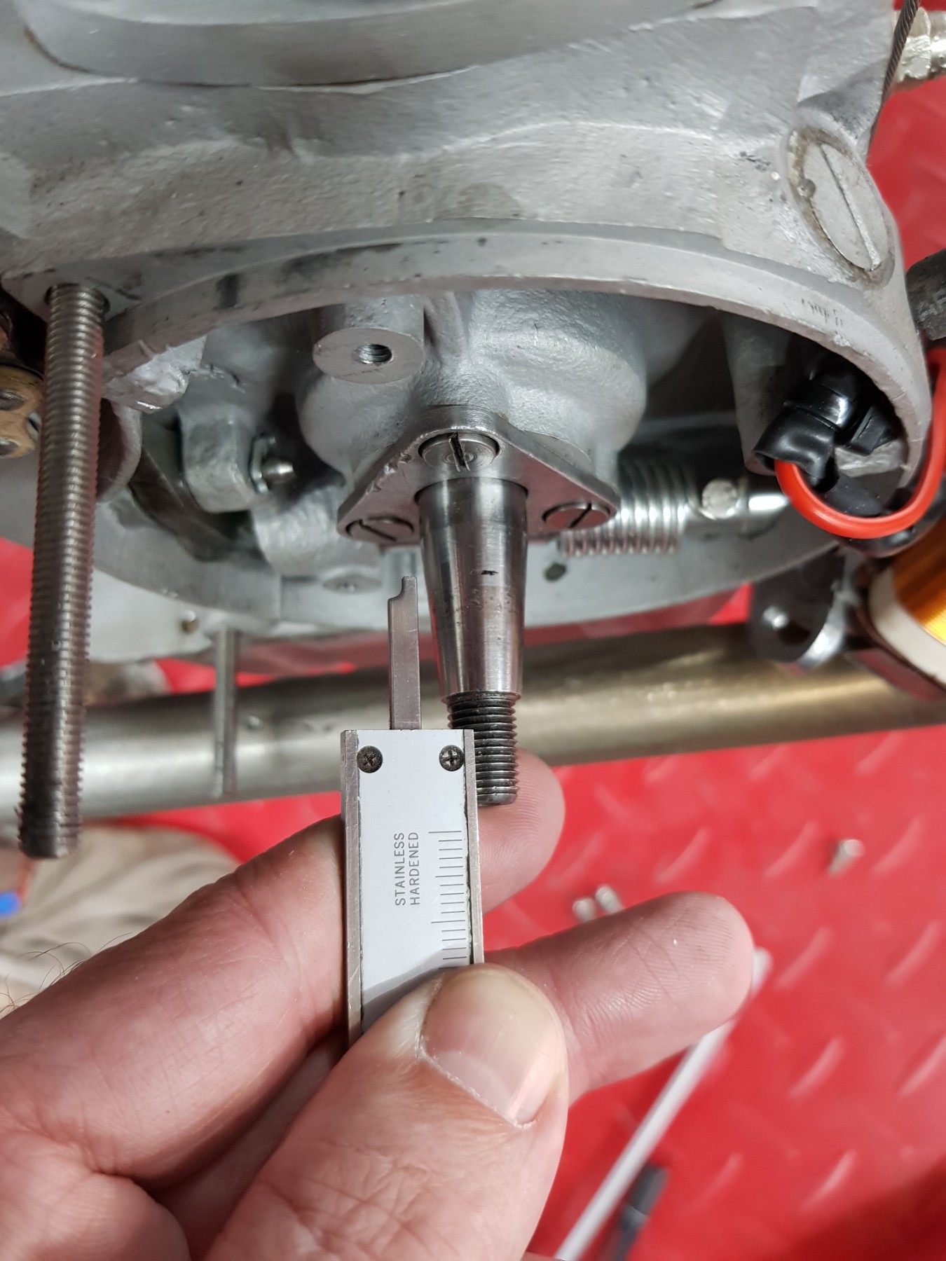
Tapper length 21,5mm
Tapper length 15mm
Investigating iff this works
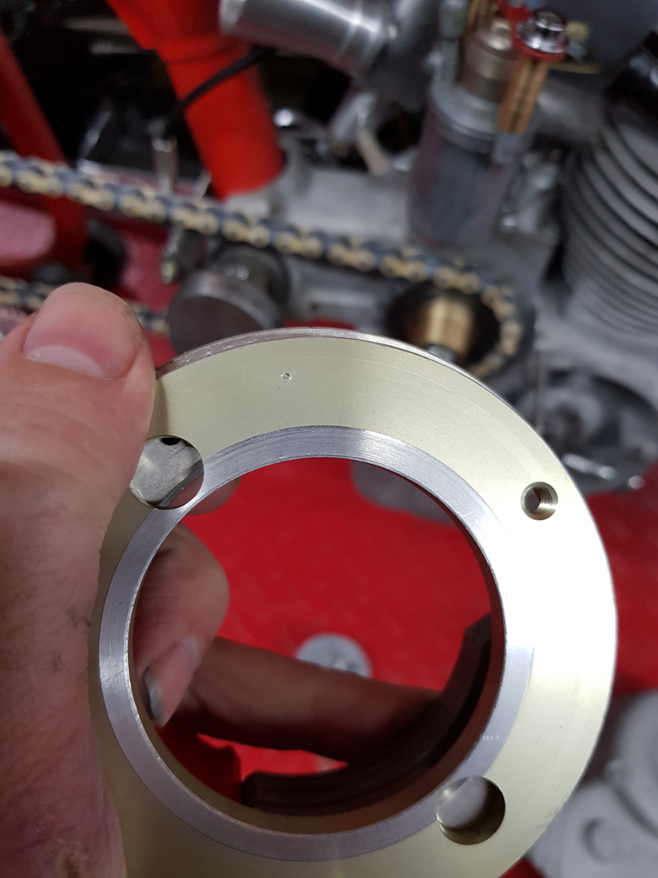
Rotor should fit the Motom
The 068R030
Curve may work on a Motom
The: 068C068
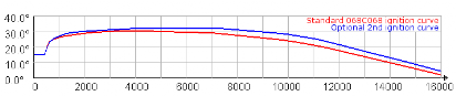
First impression is good.
The tapper/cone is correct.
Two of the three bold do fit, perhaps a tiny modification will make three bolds possible
Cover still fits.
First impression is good, think this may work.
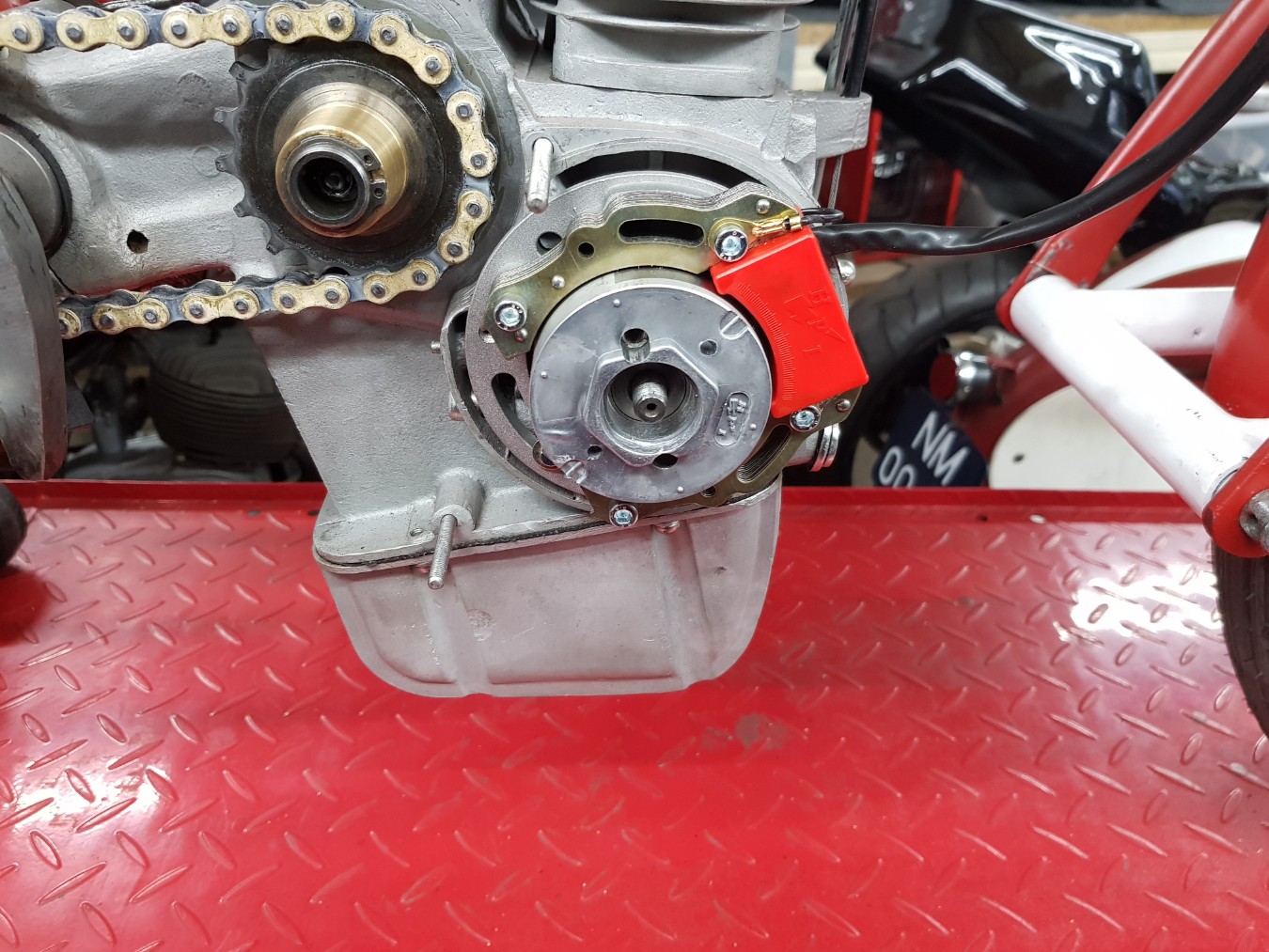
The idea is to use the second curve from the CDI but with the base plate lowered so the max advance is about 28 a 29 degrees
My Motom engine will have its performance between 2000rpm and 6000rpm
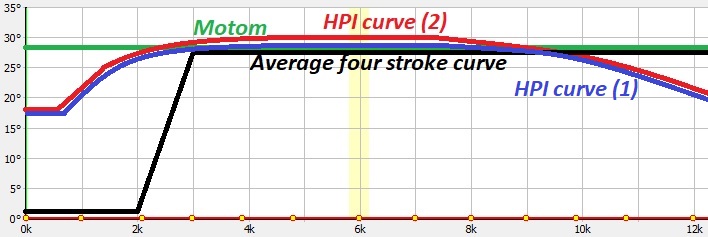
The original Motom curve will be a flat and steady curve because of its fixed point.
The HPI curve only second curve will be used for max HP.
The stock fourstroke curve an example of a average ignition curve.
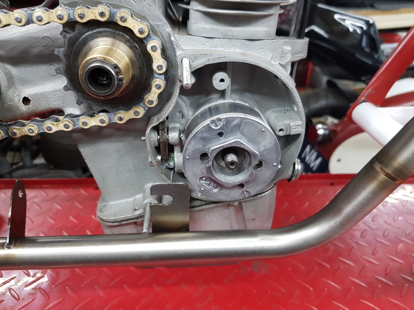
With a bid off, turning all three bolds fit.
Need to investigate if this is acceptable.
Had to use the base plate because the rotor was sitting too high compared with the stator.
Also, I could adjust the ignition better with the use of the base plate. This could be useful when I need to fine tune the timing point.
Starting to change the base plate.
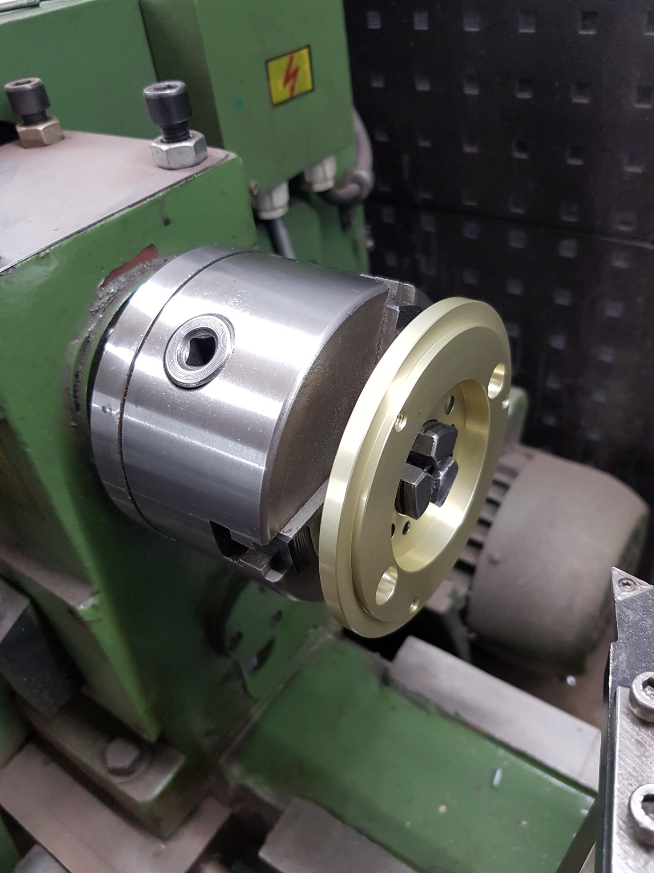
Enlarged the inner diameter.
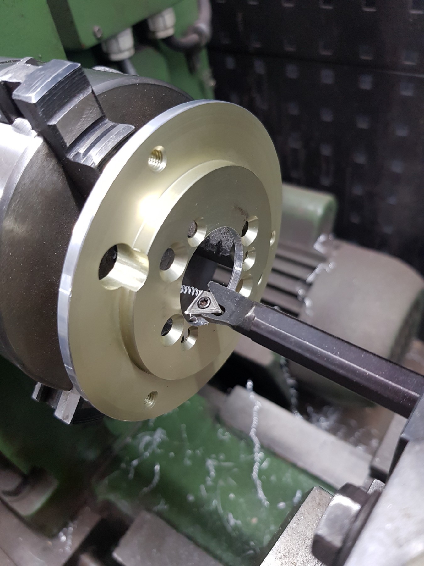
Max internal diameter.
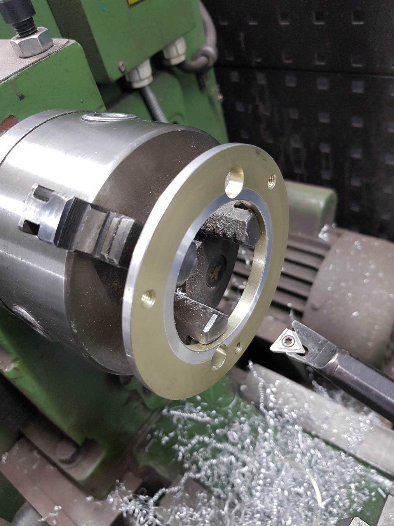
Changed the service.
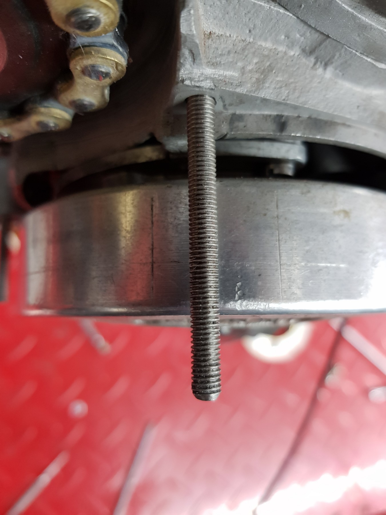
Making a marker tool.
Tiny but OK
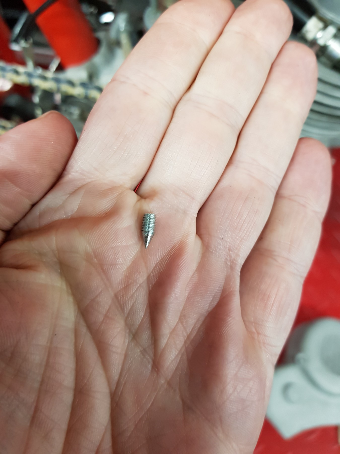
In to its place.
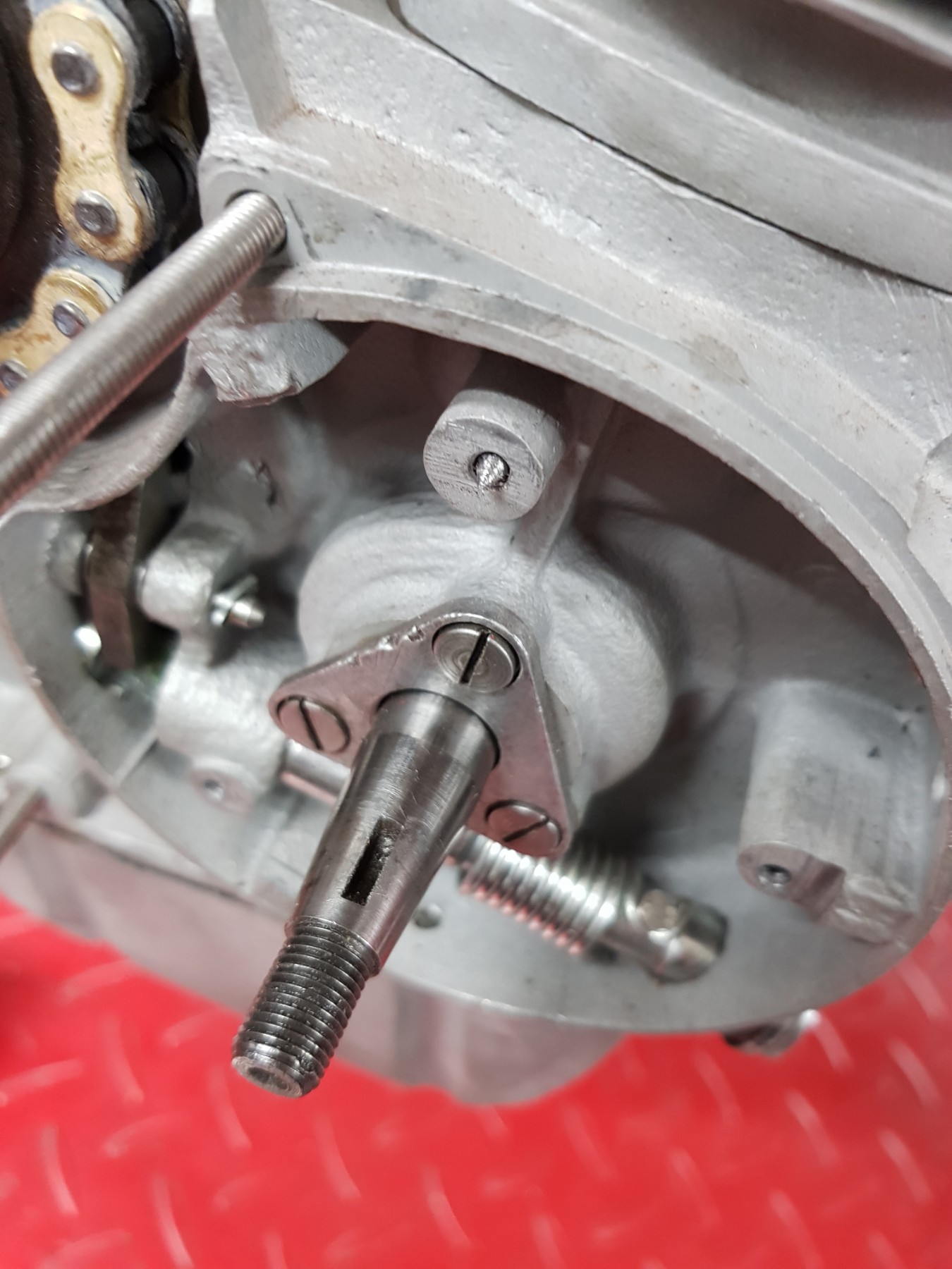
Giving a clean mark.
Using countersunk bolts, so the stator also locks them when mounted
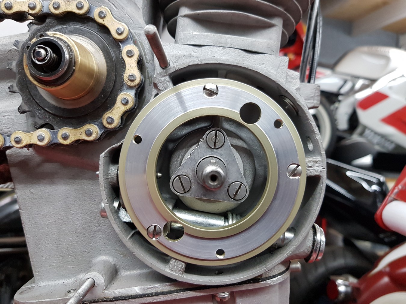
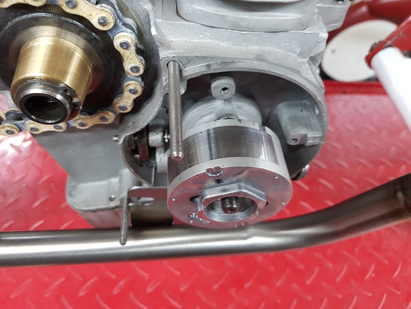
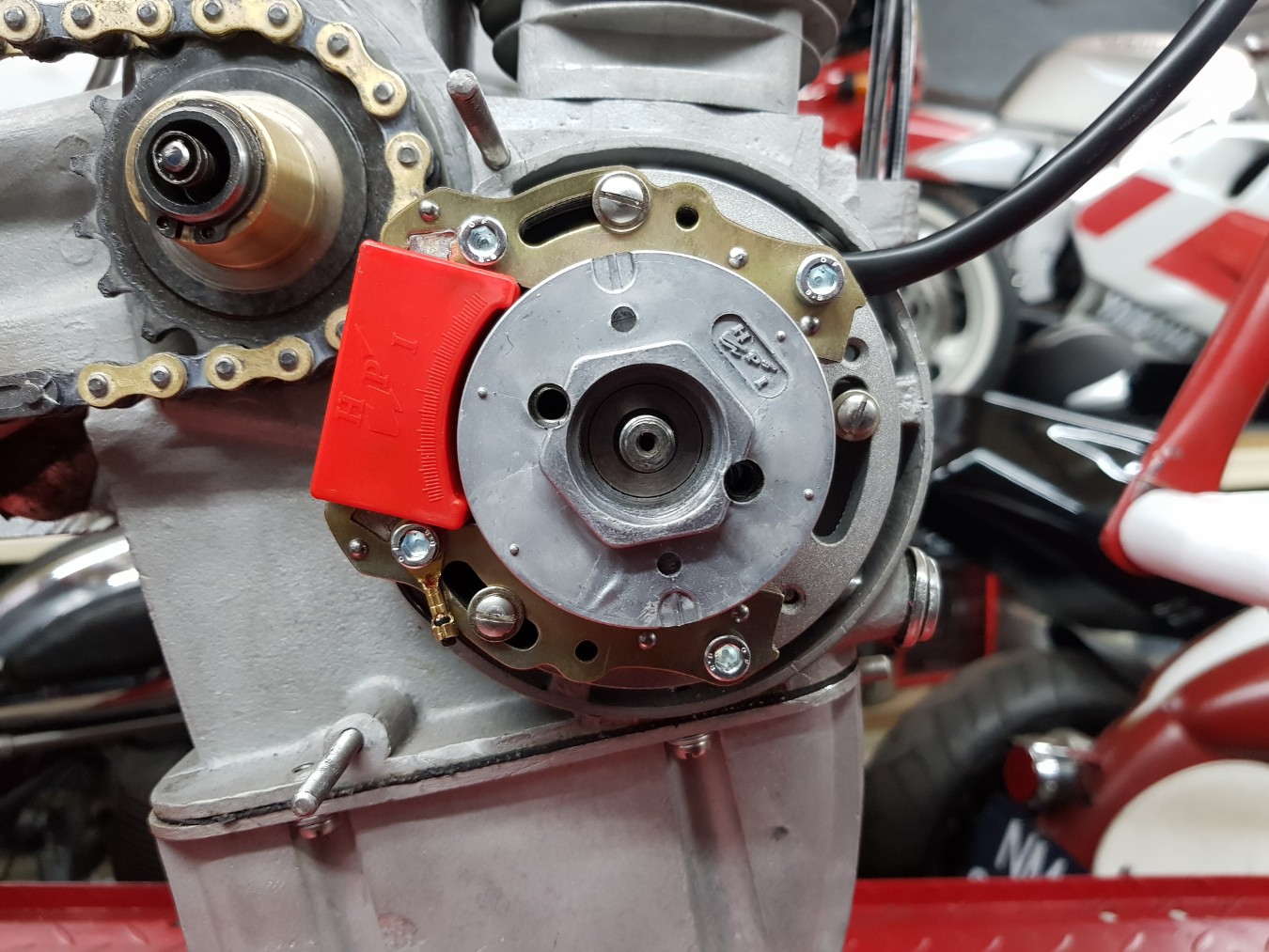
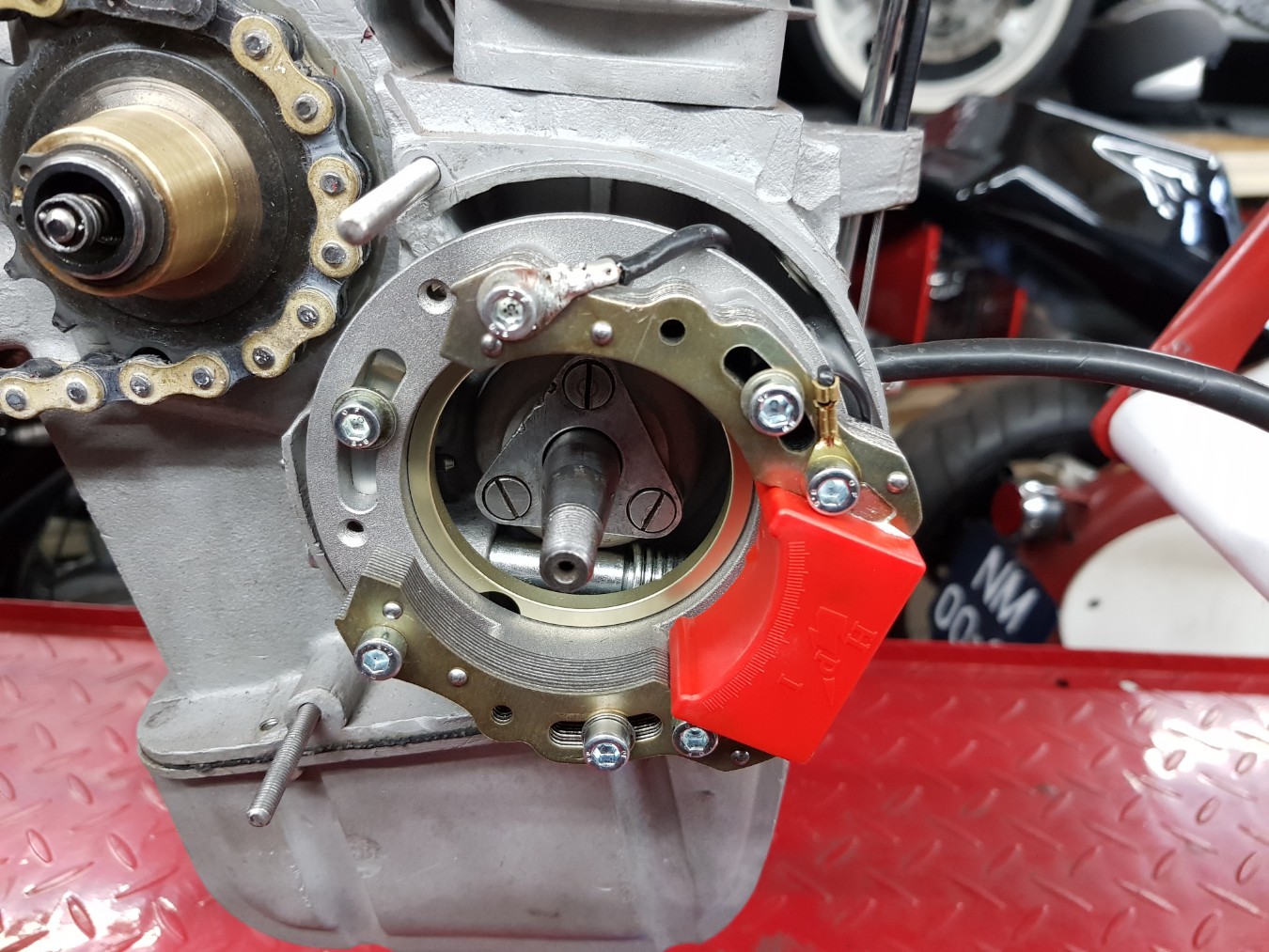
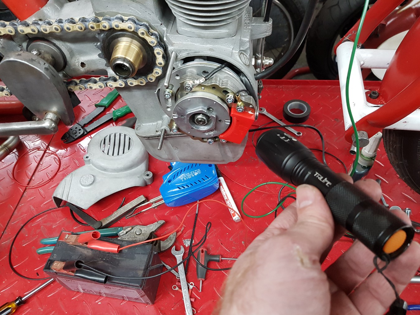
Stator mounted.
Rotor mounted.
Cover mounted
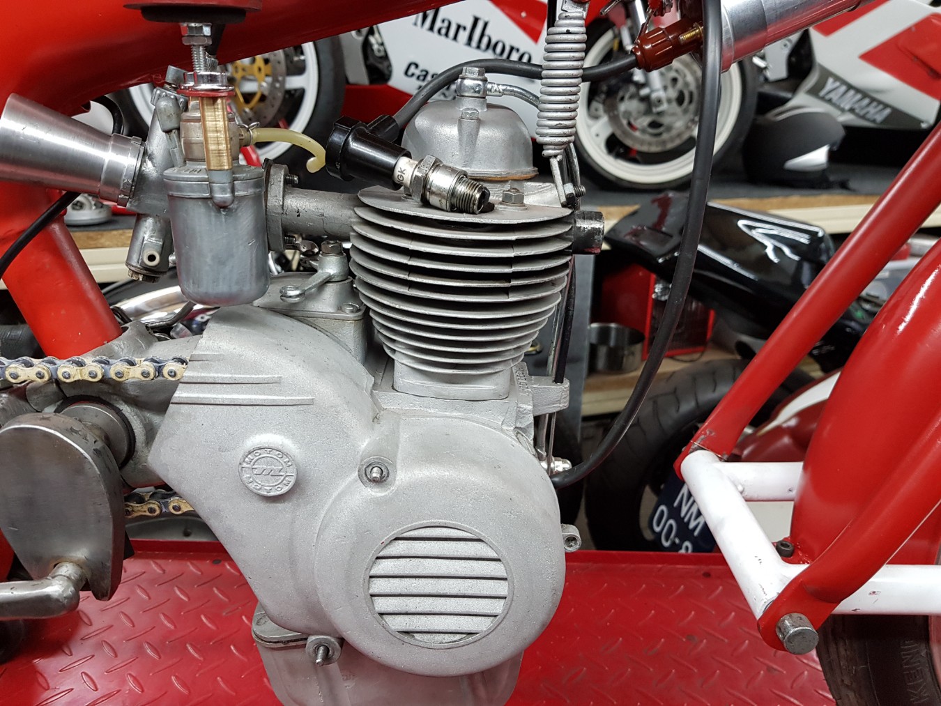
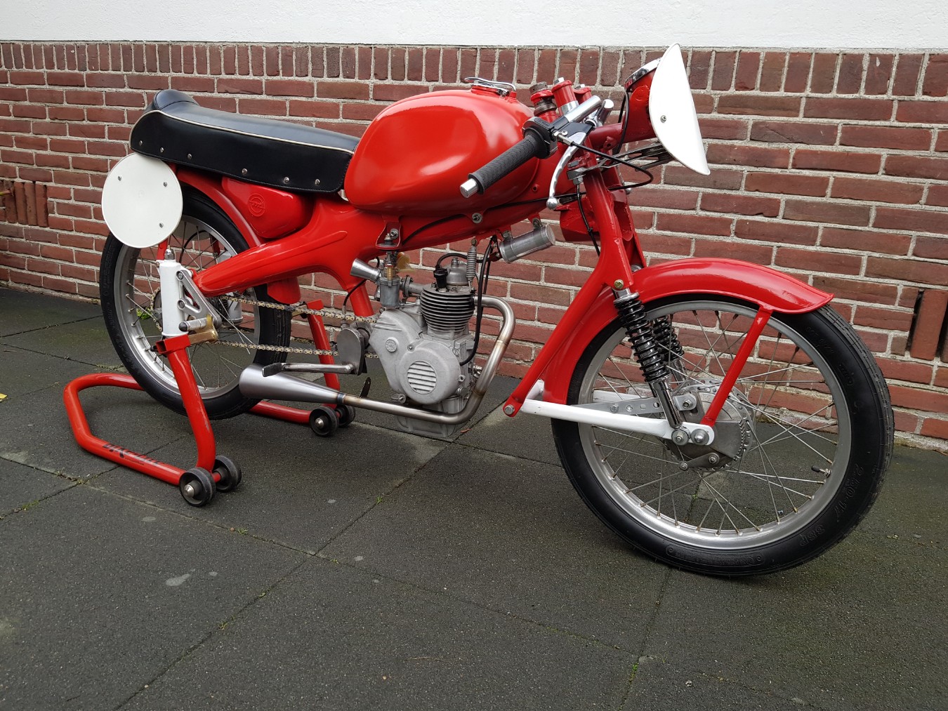
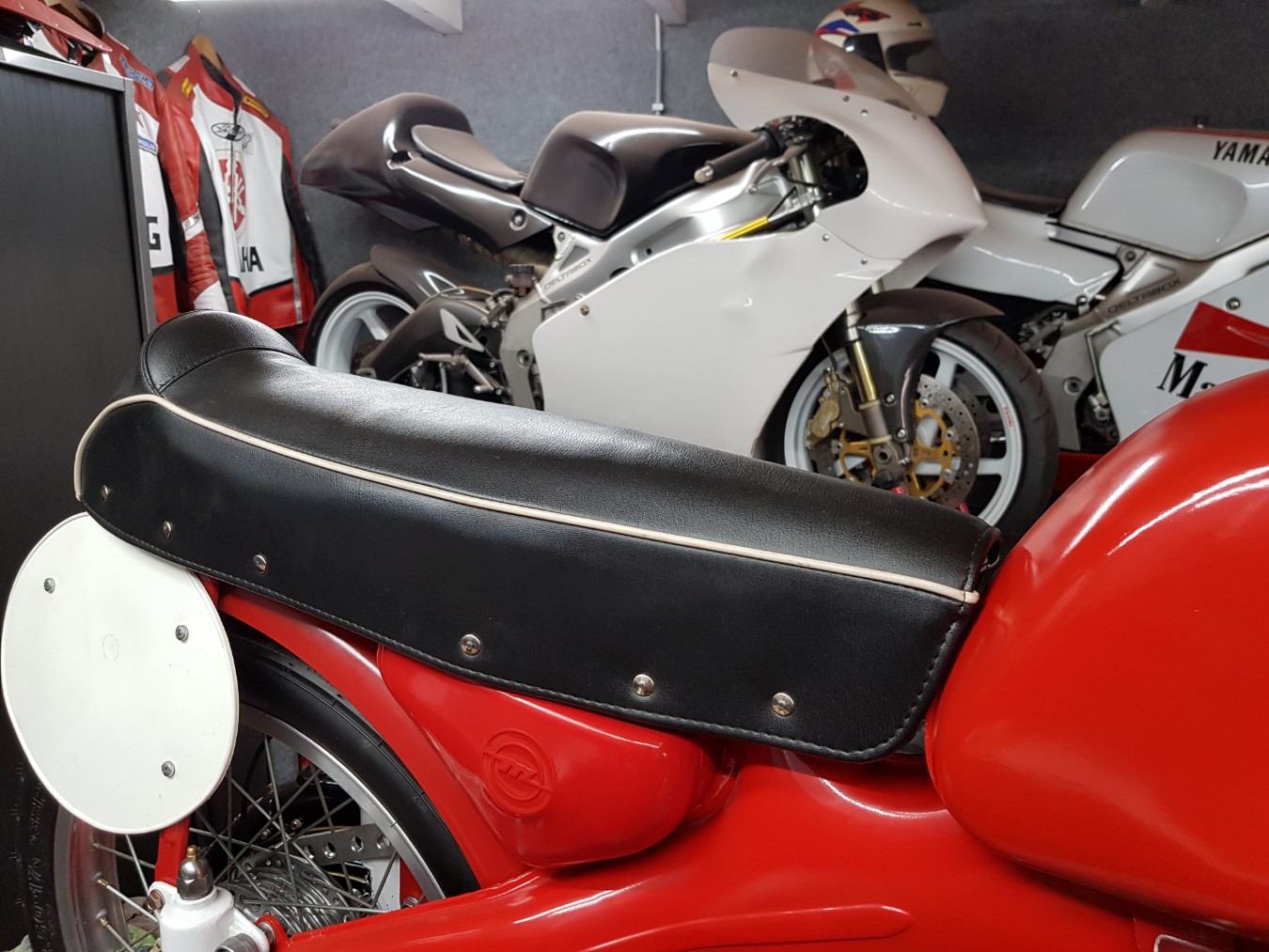
It still looks like an stock ignition.
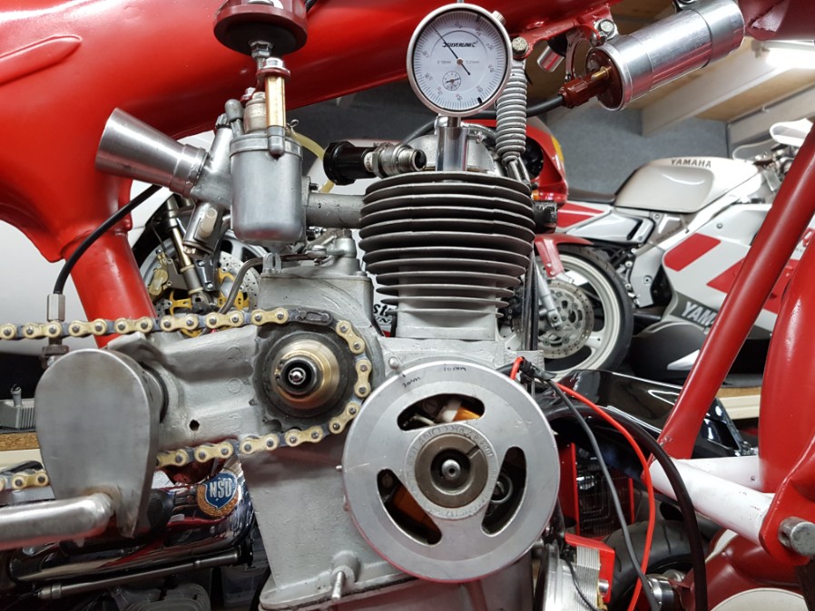
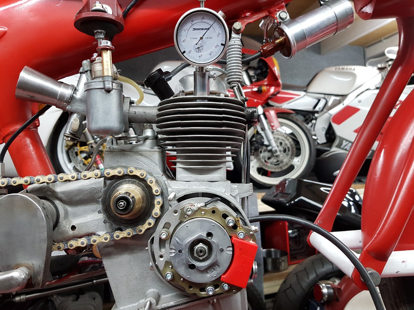
Finding the original ignition point.
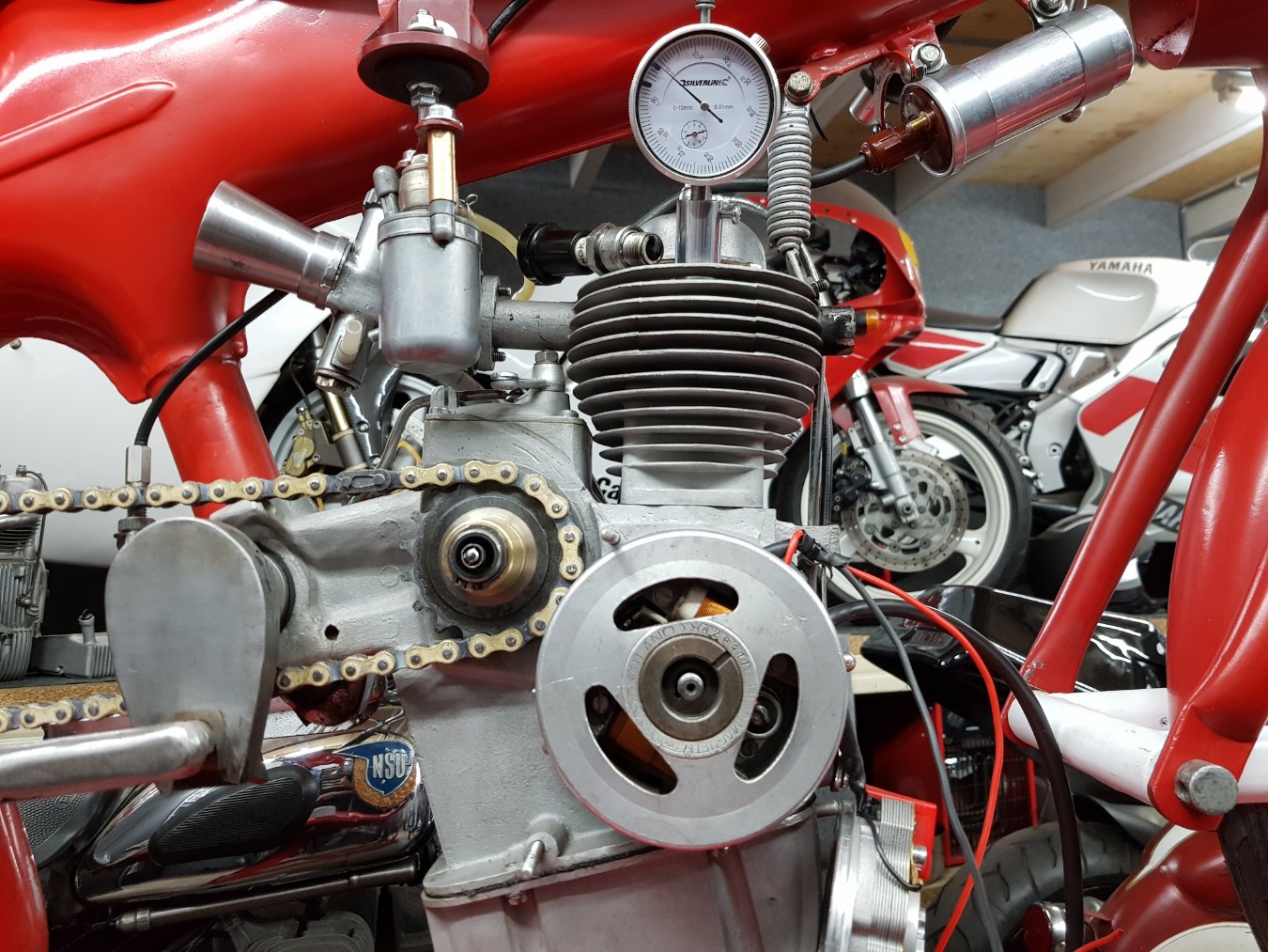
Original marks.
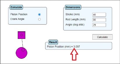
The ignition point is at (around) 3mm that is 29 degrees.
But it's difficult to measure so think I'm close with saying its between 28 a 29 degrees.
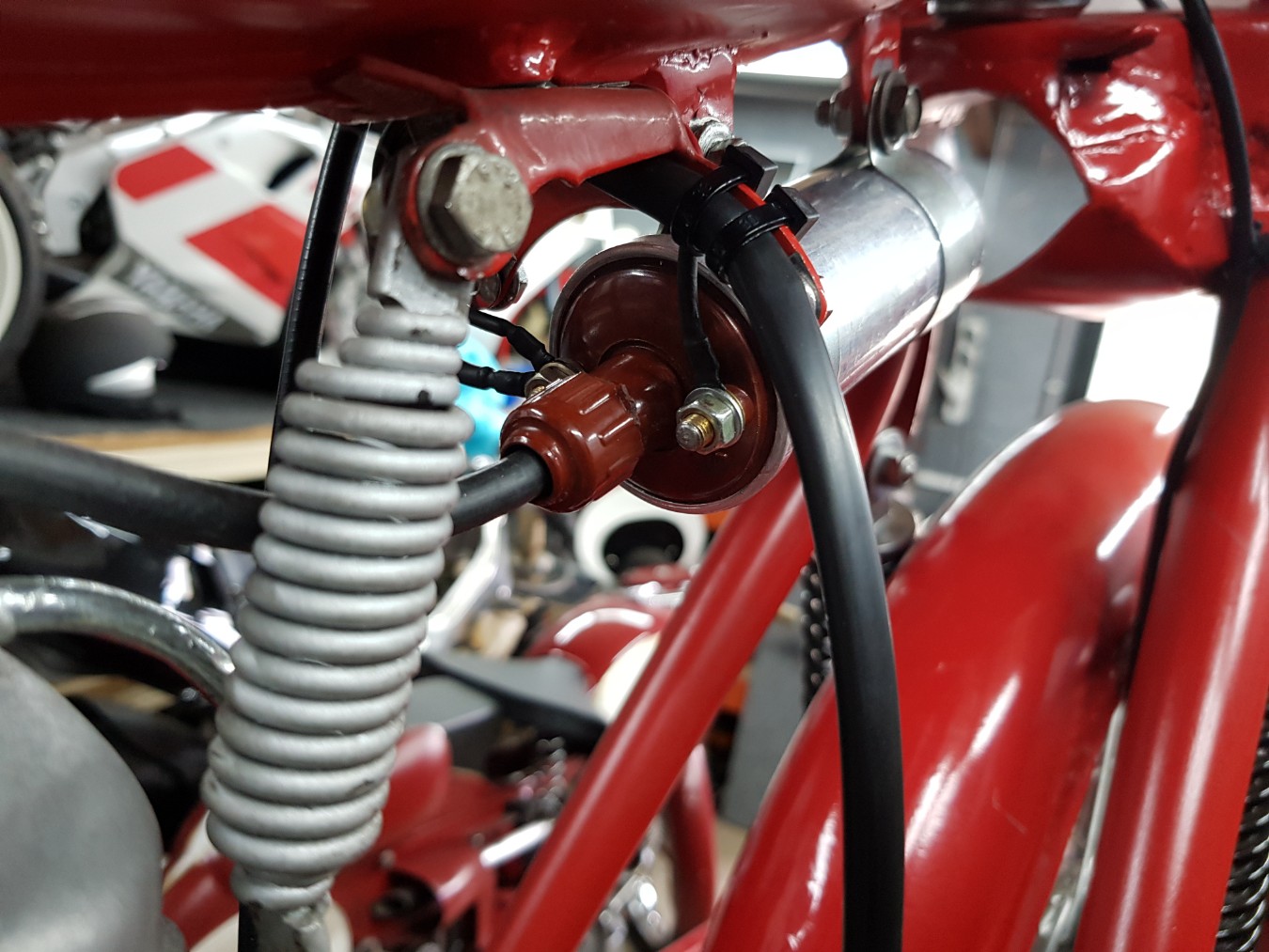
Made a big ground cable for the ignition coil so I'm sure that's OK.
Ground cable goes directly inside the wiring loom so I will have all the wires at the coil.
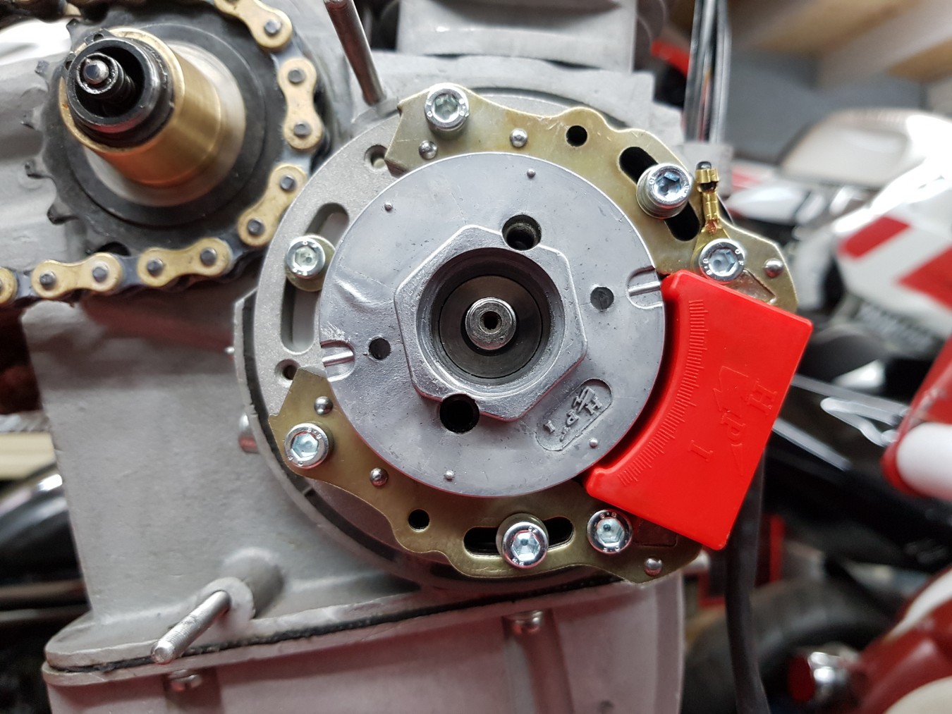
Manually setting up the HPI ignition, at 2mm like the manual says.
Placed the CDI underneath the seat so I can access the CDI.
The cables for selecting the ignition curves.
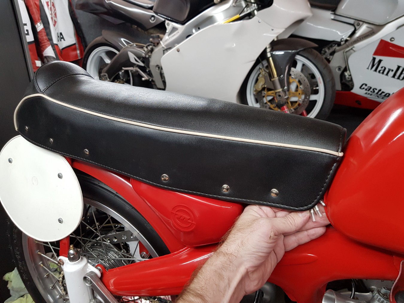
Easily pushed away so all is clear.
A nice tight bent.
Trying to keep it as clean as possible.
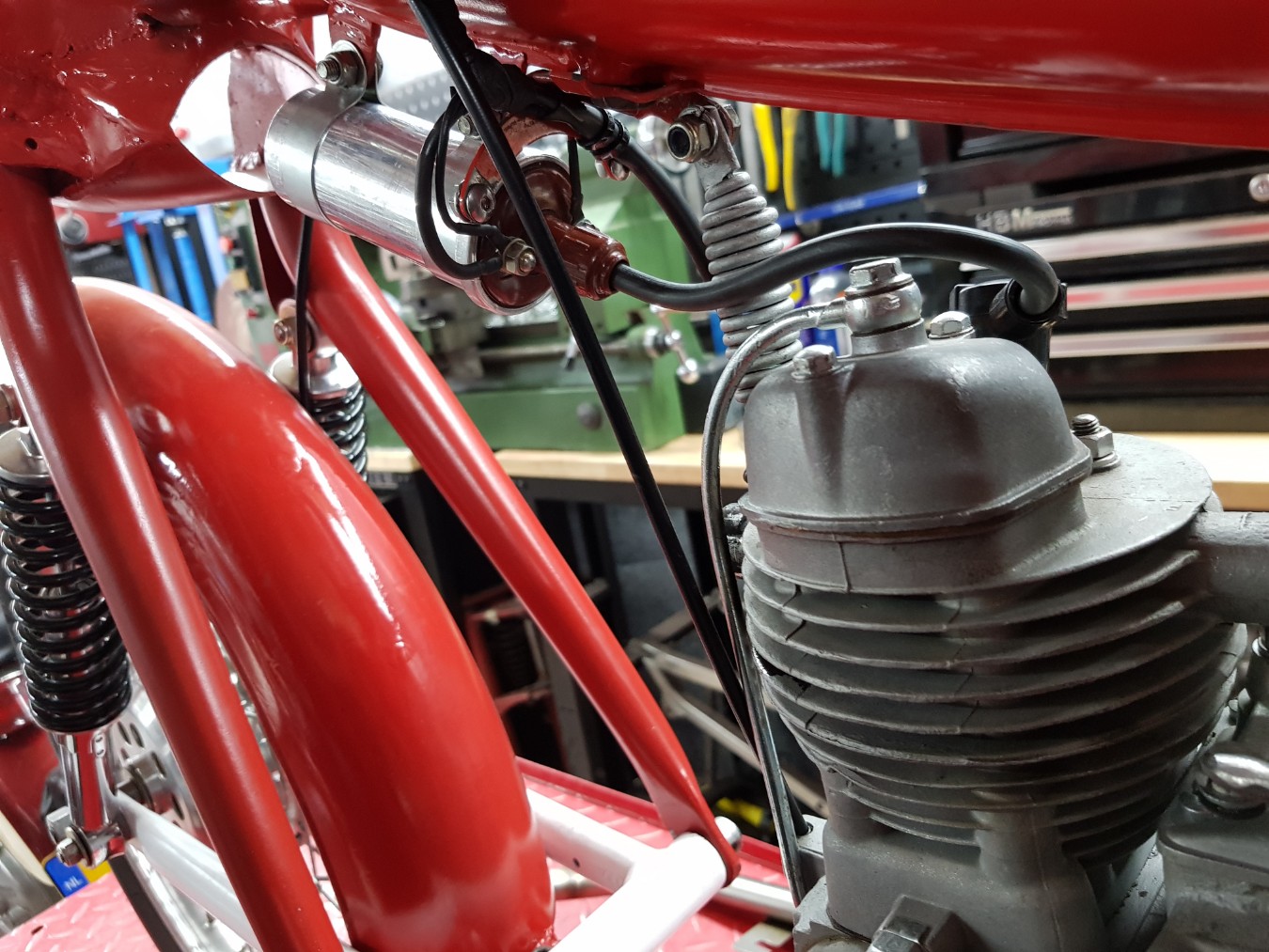
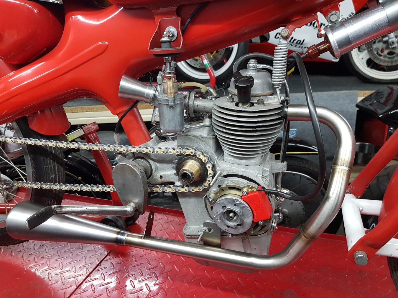
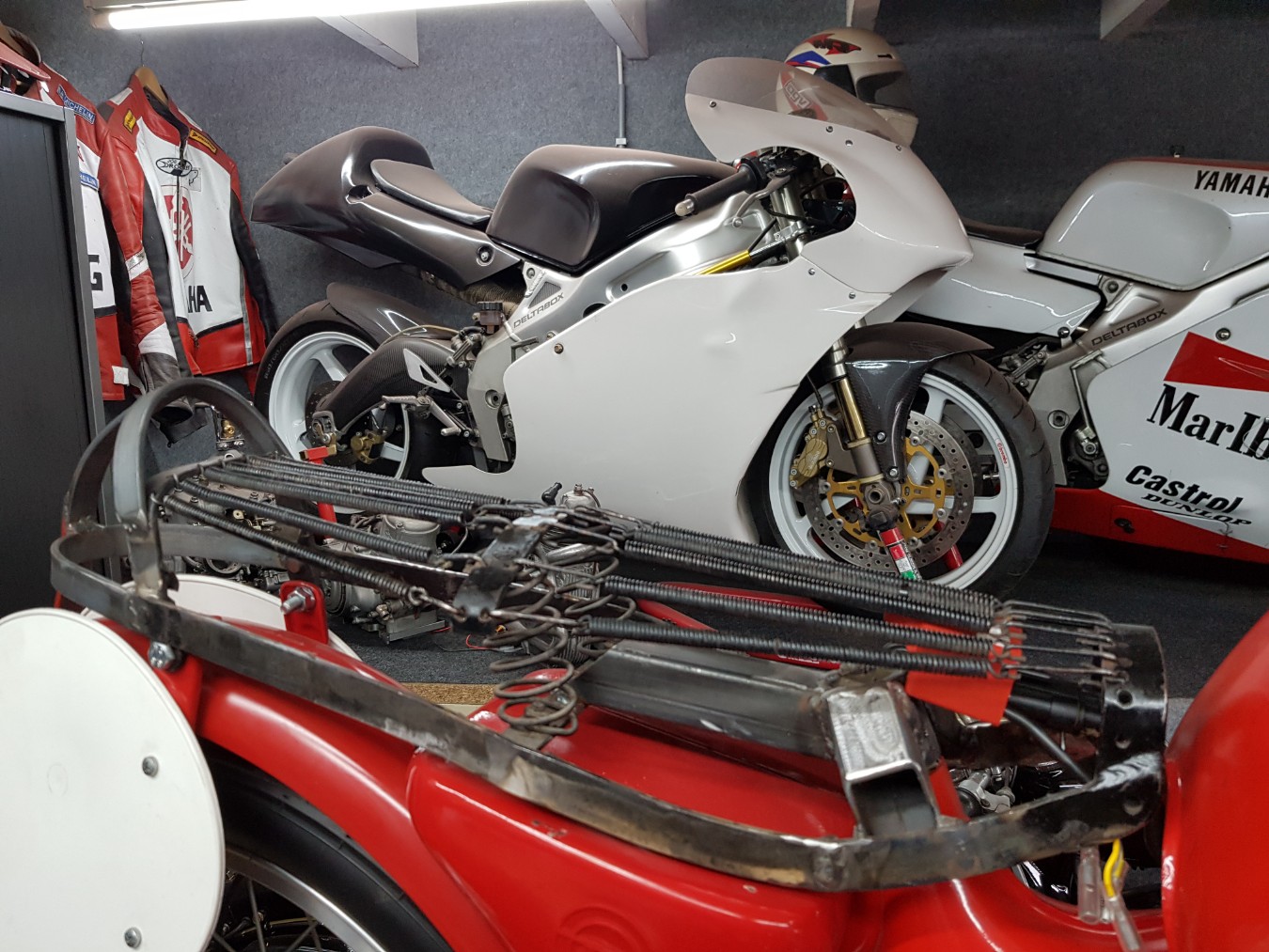
Looking at the end result.
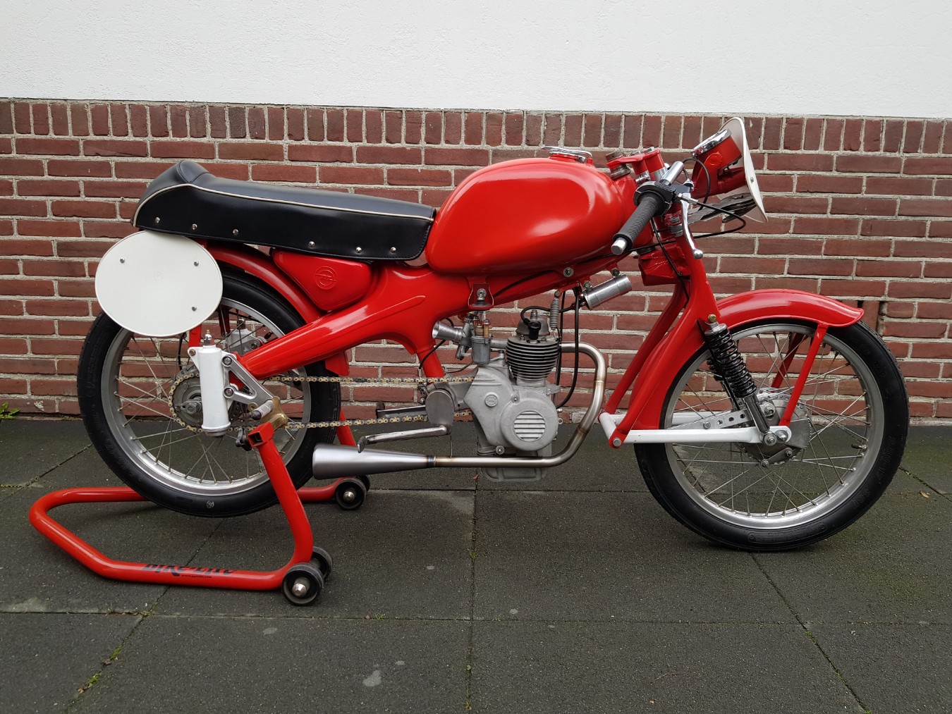
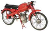
The Dellorto is looking good.
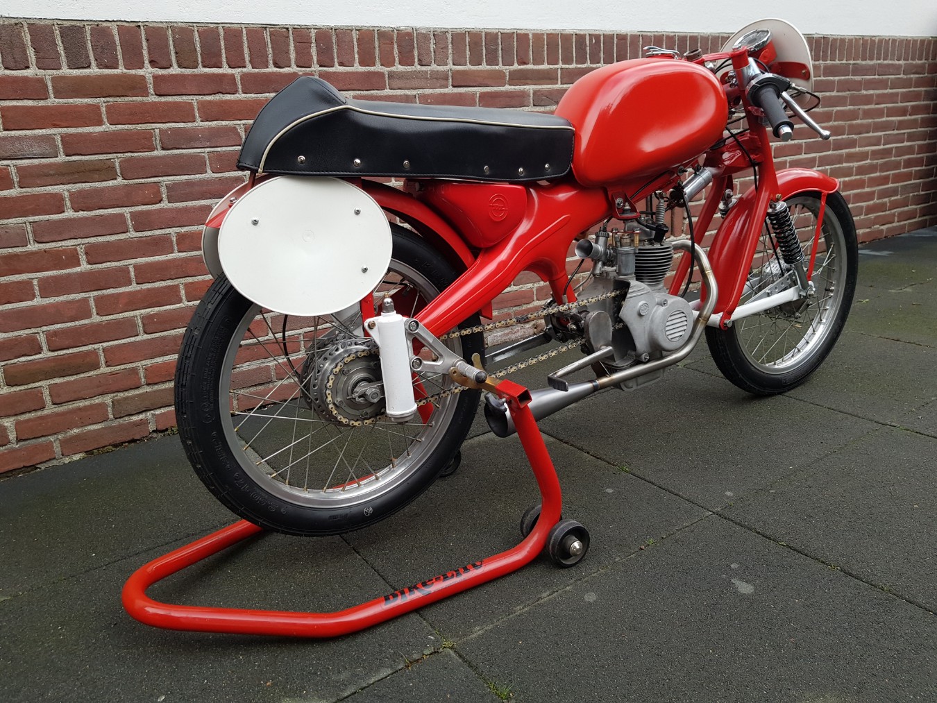
Also exhaust is looking good.